
Robotic arm
I have always been interested in the construction of robotic equipment! I have no need to make anything... until now! Some months ago I saw the movie "I, Robot", and decided "it's the moment!, I want to build a robotic arm!".Here I present the results, hoping it will be useful to other people who are also interested.
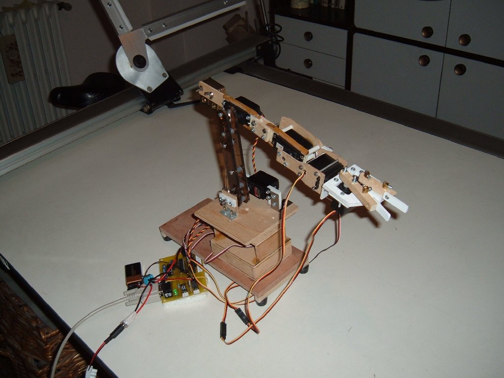
This robotic arm is a little demonstration, it uses stock servo-motors normally used in RC models, and is controlled from a pc, attached with a serial cable.
Mechanical structure
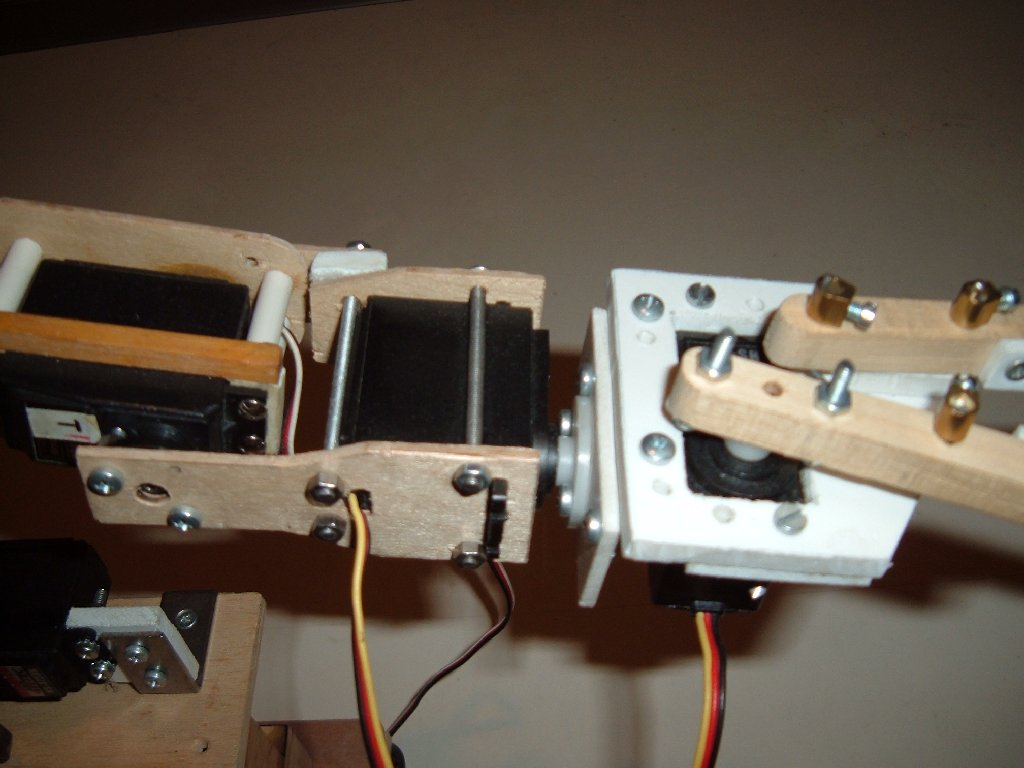
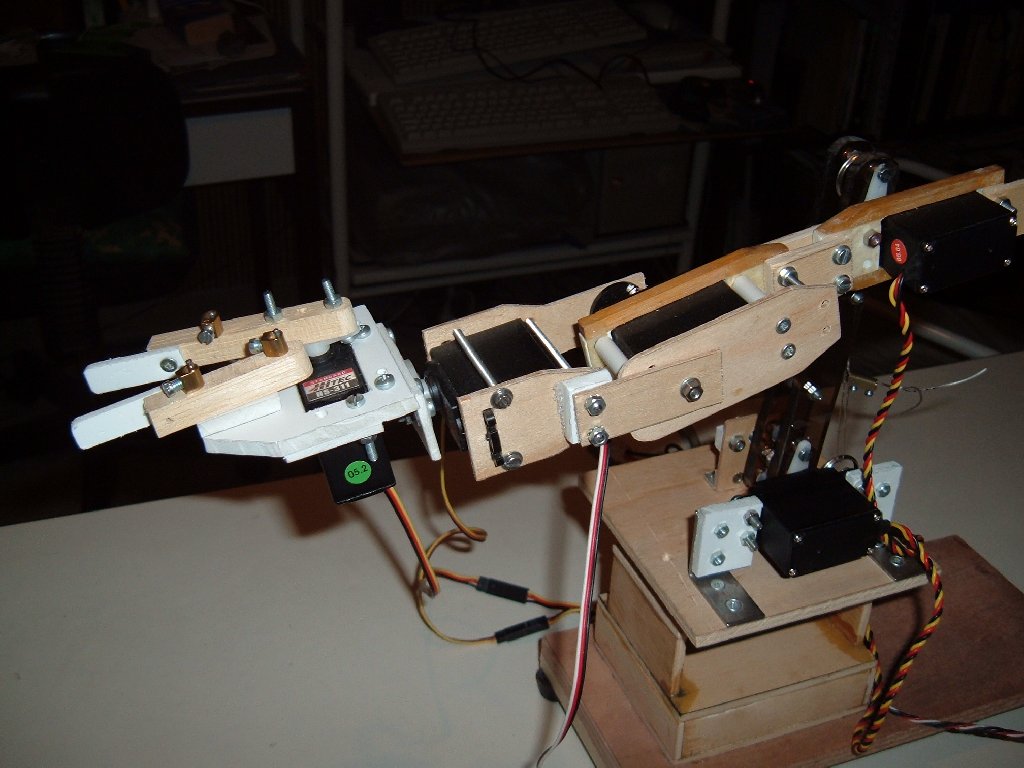
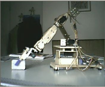
The arm has 5 degrees of freedom: a rotating base (pivot); a "shoulder" motor; an "elbow" motor; two "wrist" motors, one for up-down movements and one for left-right rotation. And the arm has a sixth motor for a gripper.I made some different designs of the various parts, these are the best "thought of", the result of many "make and try"! Now it resembles the structure of real industrial arms.
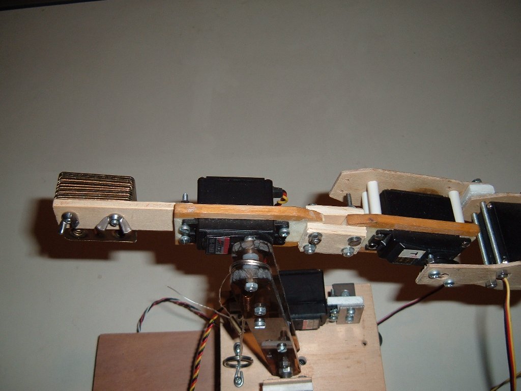
The length of the part between the elbow and wrist is almost equal to the length of the "hand",( this allows a good balance of the weights) allowing equilibrium.
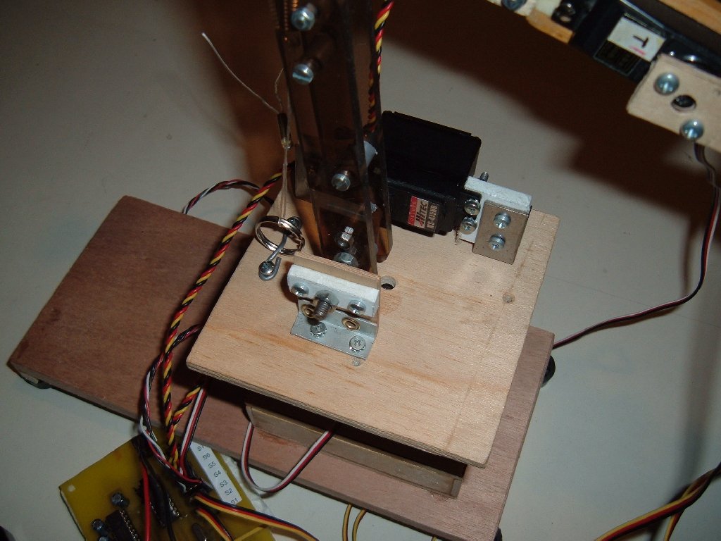
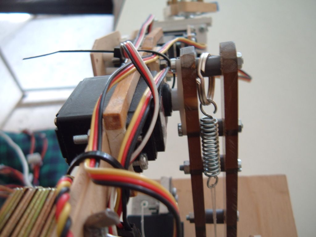
The shoulder servo is "reinforced" by a spring when the arm is inclined forward. In this position the load on the shoulder servo is maximised, rapidly decreasing when the arm returns to a vertical position. Using the spring allows the use of a little and less expensive servo.
The shoulder servo absorbs the weight of the arm. To help it the vertical arm has a pivot, rotating in a support joined to the base. It creates a more rigid assembly.
The horizontal part ("forearm") is counterbalanced with a weight opposite to the gripper. Then the elbow servo is partially unloaded from the "parasite" torque generated from the wrist and grippers own weight .
The base has steel plates bolted underneath, corresponding in position to the arm. This helps to acquire the necessary stability, also when the arm is totally extended horizontally.
The materials I used where mainly plywood and pieces of wooden dowl, "because I have a lot of these", and it's easy to work on it with my simple tools (drill mini drill, saw, etc.). Indeed I built many parts with a special plywood for air models, it's only 2 mm thick but very rigid and strong! Maybe better than aluminium. Some parts are made of white plastic (PVC) or semi-transparent plexiglass, also good materials, and easy to work with.
Many parts are joined with screws and bolts (3 or 4 mm diameters), some others are glued with epoxy or similar glue.
I use these servos: 2 Hitec HS475-HB for the shoulder and elbow, the joints with more load; 2 Hitec HS311; 2 Futaba S148. A standard servo for the gripper is a bit cumbersome, but I tried a little Hitec HS81 and it broke in a few minutes of work!
Electronics
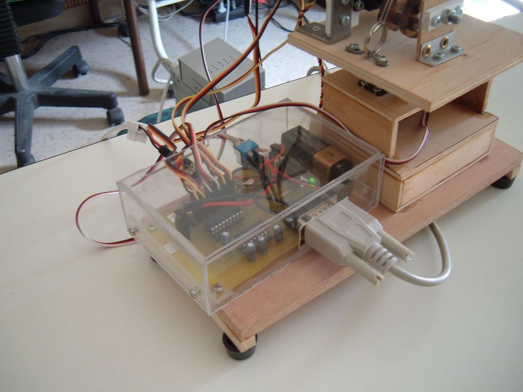
The arm is controlled from a pc by a customized electronic card. Indeed the pc cannot produce directly the precise timing pulses needed to position the servos. So I insert a control card based on a microcontroller: the microc. receives the positioning commands by a serial cable, decodes it and sends the corresponding timing pulses to each servos. I use a Picmicro 16F628 microcontroller, because it's very easy to program, and in Internet there are thousands of tutorial and examples. And last but not least... it's very cheap!In a first try, I used a 16F84 with a 4mhz clock. But it has no hardware UART for serial communications, then it's almost impossible to obtain a plain and smooth work, many commands where lost in the serial transmission (at less in my knowledge, I am a newbie in electronics!).
Instead the 16F628 has the hardware UART, then it can receive serial commands really while processing the pulses for servos without losing anything. But again 4 mhz are too few to obtain a smooth work, I observe some "glitches" when the reception of a command interferes with a pulse on a servo. The 20 mhz clock removes also thats.
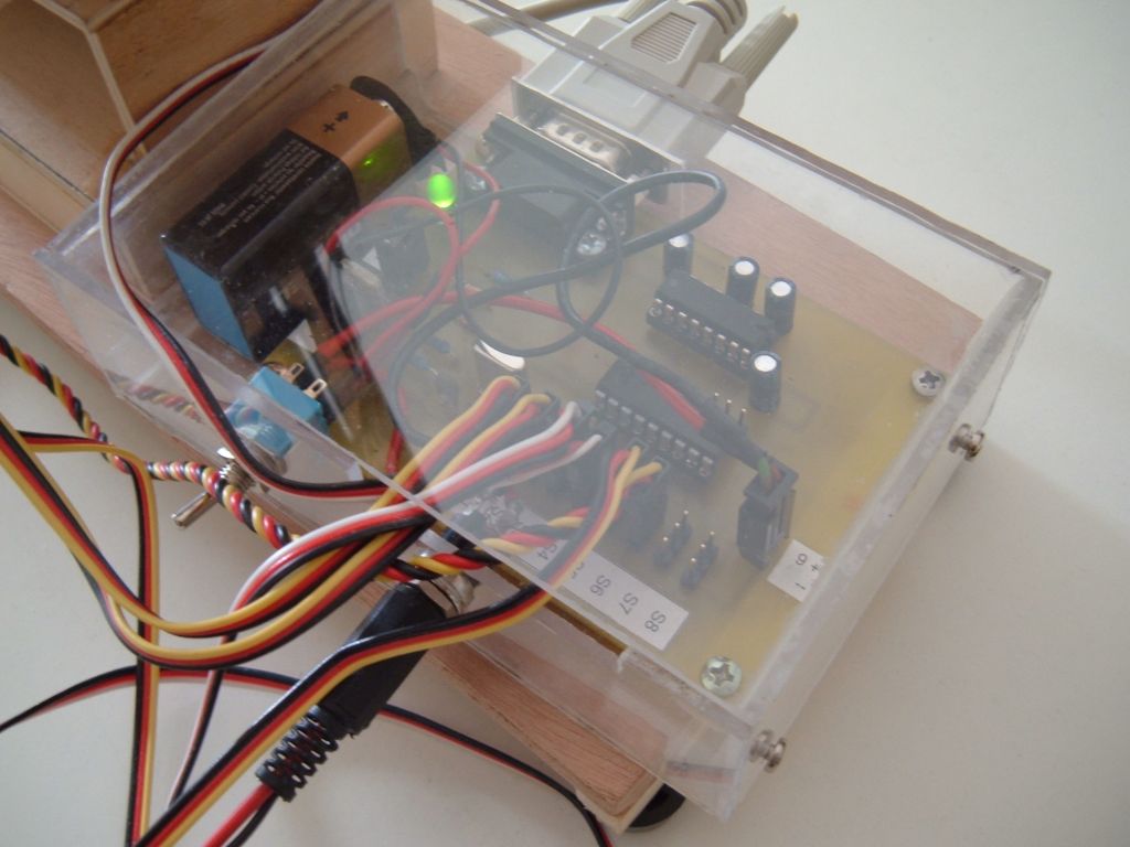
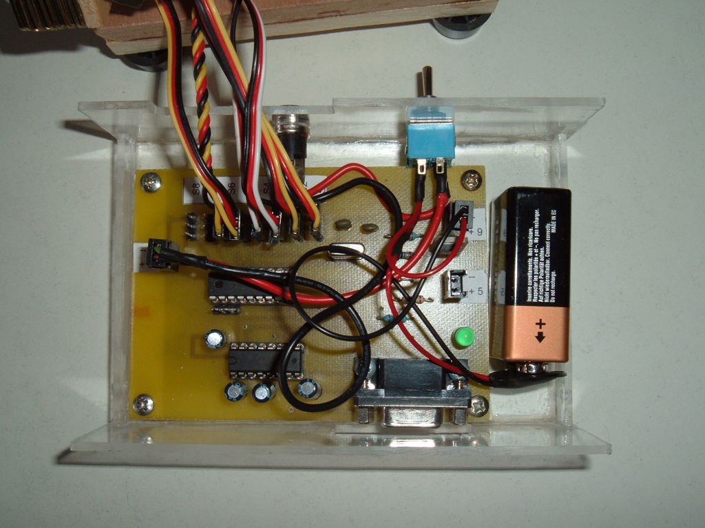
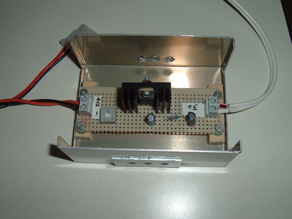
The circuit has: separated power supply for logic (5 volts by mean of a 9 volts battery reduced from a Lm 317 i.c.) and servos (6 volts from a old pc transformer, with another Lm 317 circuit to reduce from 12 to 6 volts); eight attacks for servos, although only 6 are used for this application; a serial female connector, allowing the microcontroller to read and write to pc by a MAX 232 adapter ic; a connector to connect others devices to 5 volt voltage and ground; another connector for the 3 free pins on 16F628.
The firmware on 16F628 is written with the very good MikroPascal from MikroElektronika. The program uses always interrupt routines to manage all timing and serial receive. The protocol of the commands is very simple, with three data bytes and a check byte to verify the exactness of transmission.
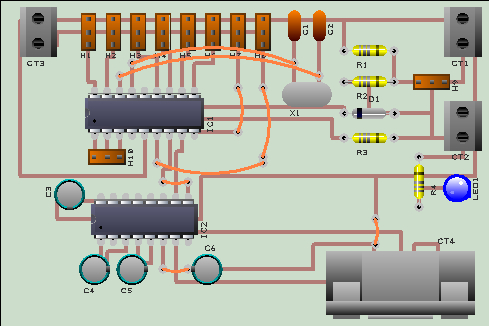
Control card schematic
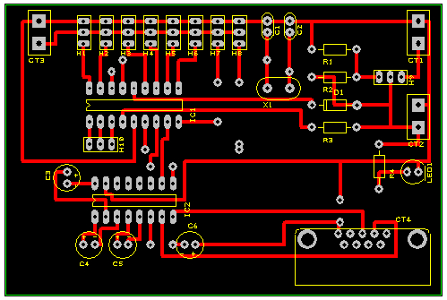
Control card PCB (my first PCB layout! Not the best possible, of course...)
Control card PCB layout
12v to 6v circuit schematic
16F628 Pascal source
16F628 program in hex format
Component Layout
Silkscreen Layout
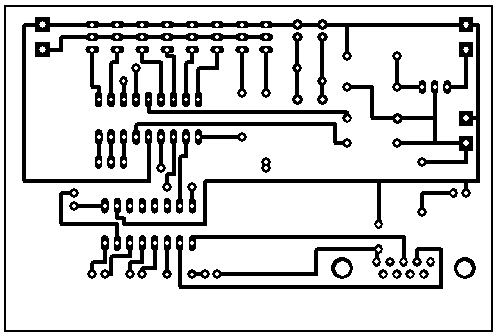
Artwork Layout
Control software on pc
The control program on pc is written in Delphi Pascal, under Windows. I appreciate very much Delphi, because it compiles directly to the exe, without the need of any external dll. And the programs are also fast.The control program allow to control the arm by a joystick or joypad. Any of the sixth servos can be controlled separately with the buttons on the joypad. Because I have a joypad with 4 buttons plus the central "cross" buttons, I have implemented one of the buttons as a switch to change from the control of the first 3 servos to the other 3 servos. Of course if you have a joystick/joypad with more buttons you can make the program simpler.
More, the control program can record a sequence of positions of the servos in a script, and replay them automatically. This is a sort of "learning" mode: you move the arm to one position, record the position of one or more servos in the sequence you want, then move to the next position an record again, and so on. The program incorporates a simple editor to edit the script.
Finally there is a mode to position the gripper by absolute coordinates, in centimeters. The X coordinate is the horizontal left-right, in respect to arm; the Y is the vertical up-down; the Z is the horizontal forward-backward.
Delphi control program exe
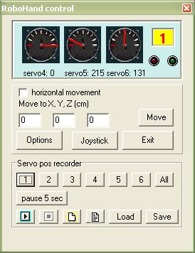
Photo gallery |
||
|---|---|---|
|
|

|
|
|
|
|
|
|
|
|
Movie of the arm in action
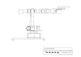
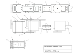
Project drawings |
||
|---|---|---|
 |
 |
 |