
The GDS-1 robot
GDS-1 robot is my
attempt to build a "home" robot. An
home
robot should be an useful tool for some everyday work, not a simple toy.
Two simple services, that a little home robot can
attend, are cleaning the floor, and bringing an object from a room to
another room, as a sort of automated trolley.
Another decision I took was using mainly video
camera
captured image as the main sensor, for the largest possible
number of goals: obstacle avoidance, localization, guide, etc.
The last goal was to use the maximum of "green"
materials: wood, metal, screws instead than glue, fabric.
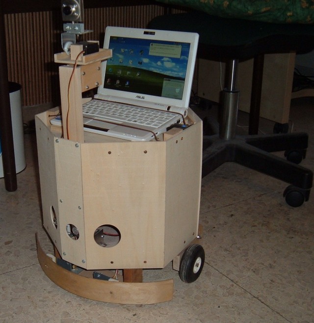
The final result is GDS-1. It is a little robot, capable
of
cleaning floor, has a large amount of functions based on vision, has
(some, for the moment) capacity of auto guide to a target place, or
can
follow a path line on floor.
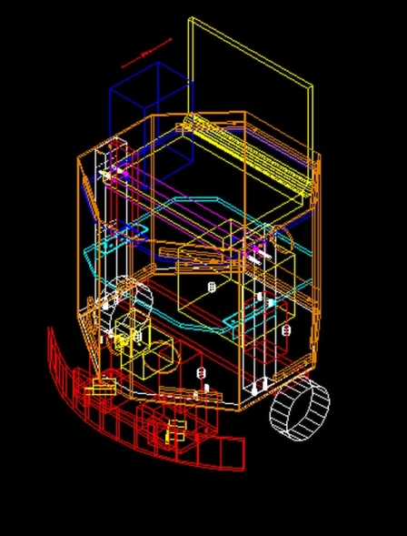
Mechanical structure
The main structure is a robust wood framework, where a base plate supports a rectangular "arc". The arc supports two shelfs. The three planes (base plate and two shelfs) bring all electronics and batteries, the guide computer, video camera support, power cables and switches, the cleaning motor, etc.Under the base plate are fixed a couple of drive motors, the forward bumper support, and the rear cleaning device.
The external body is made from flat panels fixed by screws to base plate and shelfs borders.
The final aspect is as a little polyedrical prism, not so bad in my opinion.
Every body panel can be removed independently from the others, having his own fixing screws. The back panel brings the general power switch, and is hinged for fast opening, in special to attach recharge device to batteries.
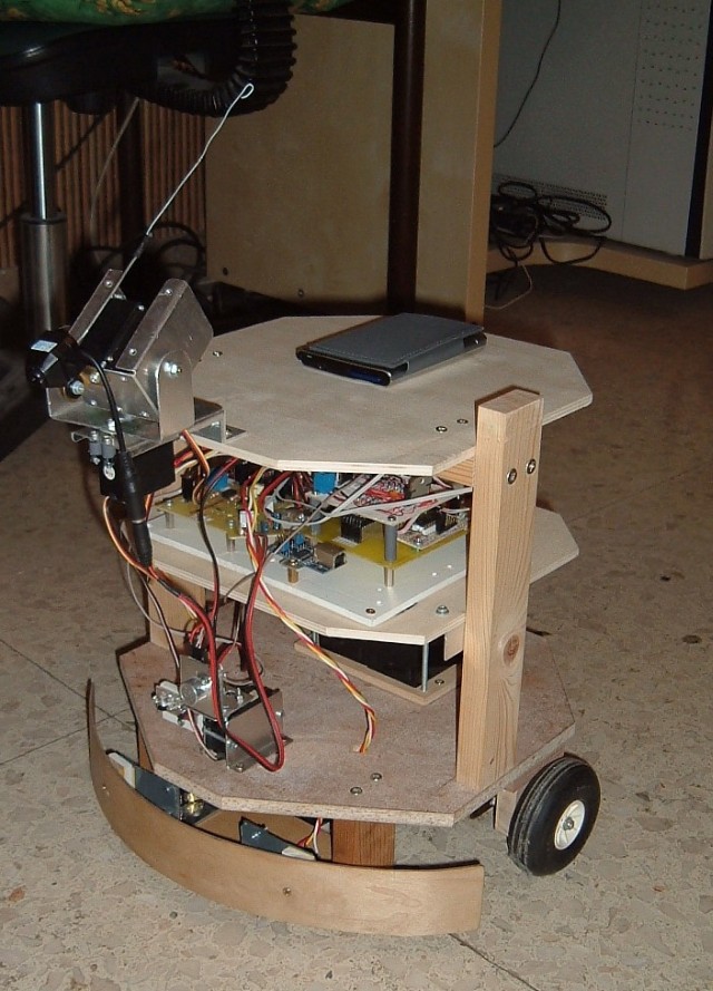
In the image is visible the internal robot structure, with a prototype of pan/tilt support, a wireless camera, on top Palm computer as trasmission device, the electronics cards, and the sonar with pan servo on bottom.
Power arrangement
The robot takes energy from a 12 volt electric battery. Indeed there are two big commercial 6 v batteries in series, obtaining the required voltage. The 12 v is connected directly to devices requiring that voltage, especially the two drive DC motors (with gear reduction). Or it's connected to voltage regulator circuits, obtaining 5 volt for electronics and other special voltages for other parts (6 v for servo motors, 9 v for video cam, etc.)The connections from batteries use a normal multi via screw connector (mamut).
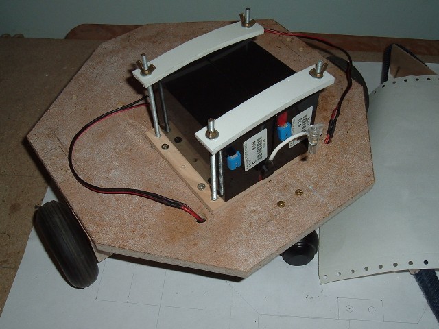
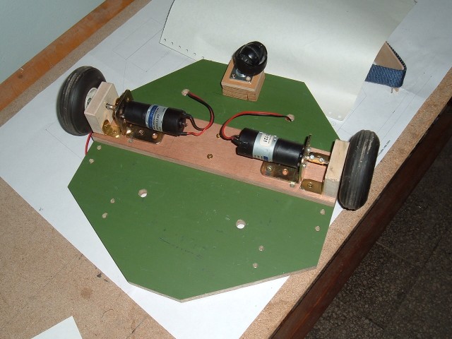
Motors arrangement in a module screwed on bottom of base plate
Electronics
The specific electronics of robot is made from three main cards: main microcontroller card; secondary microcontroller card; motor driver card. All these cards are custom developed. In total they have the following functions: communication with external pc or transmission device, by a TTL serial port; reading bumper sensors (mechanical switches); reading sonar device, by an I2C channel; controlling position of 4 servo motors; controlling status of two relais, each with two independent lines (DPDT); controlling status of a LED lamp(on/off); controlling status of the two drive motors (on/off, and rotation versus); controlling speed of motors, by pulse width modulation (PWM).So the robot can move straight forward and backward, can turn left and right, and can spin in place left and right. All these movements can be obtained at 9 different speeds (the 1 speed, the lower speed, indeed is almost unusable).
There are also some others auxiliary electronics card/circuits: a little serial-USB adapter card, it's commercial; a little card with a separated voltage regulator for special devices; the power switch circuit; the LED lamp circuit.
The electronics uses custom software in the microcontrollers, so an external pc can command the robot and receive the sensors readings by a simple serial transmission protocol.
Sensors and devices
The robot contains the following sensors and devices:- a video camera (webcam or wireless camera), mounted on a pan/tilt support with 2 servo motors
- a sonar, mounted on a pan servo motor
- horizontal bumper with mechanical switches (actually two)
- a servo motor, modified for continuous rotation, on the cleaning roller; the motor is on/off by a relais
- a bright LED lamp
Transmission device
The robot needs a mean to communicate with control device (pc). The control pc could stay in the same robot, but could be a remote pc connected by some radio channel. I decided for the last solution, because remote pc can be much more powerful, this is especially important for fast processing of images (computer vision).
So it needs a transmission device, with a radio connection, and that connection has to be easy to install on a common desktop pc. There are two types of connections that I experimented: Bluetooth, and Wi-Fi.
Initially I used a little Palm computer with Bluetooth as the "bridge" from the serial port of main microcontroller card, and a Bluetooth remote connection. On Palm was running a Bluetooth-serial port bridge program, written in C. The video camera was a wireless one, independent from Palm.
After that, I bought a net computer Asus EEEPC 900 and now I use it, in fact the mechanical structure is designed just to bring perfectly the EEEPC on top! With EEEPC I can use cheap webcam and wi-fi connection, obtaining much better images, improved range of transmission, standard programming languages/ambients. And there are great possibilities of future improving, for example migrating part or all control software from desktop to EEEPC.
On EEEPC there is a Delphi program acting as Bluetooth (wi-fi in future) to serial port bridge. The same program captures images from webcam and sends them on wi-fi connection. The "serial port" indeed is a virtual one, redirected to an USB port by a special driver.
Then the serial-USB adapter card on robot translates the USB signals to TTL serial required by microcontroller.
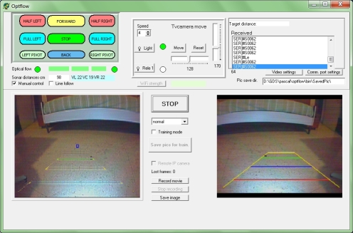
Control device
The control device is a desktop pc, programmed with a custom software. It sends commands to the transmission device of robot (the EEEPC with wi-fi), this in turn sends the command on the serial line to the main microcontroller.The sensors readings go in inverse flow: from main microcontroller by serial cable to EEEPC, then by wi-fi to remote control program.
The wi-fi connection transmit also the image captured by the external webcam (not the EEEPC internal), mounted on a pan/tilt motorized support.
With the webcam images and the sensors readings, the control program can decide how and where to drive the robot.
Of course the operator views the images captured from robot, and can send various command, deciding if enable/disable a totally manual control, too.
The software is written in Delphi for Windows, and uses OpenCV library for all image processing, plus Directshow interface for the image capturing.
Downloads
Here a general overview of robot: Download overviewHere you can download freeware CAD projects: Download CAD projects
Here you can download freeware Delphi control programs binary and sources: Download Delphi binaries and sources
If you want to buy electronical schematics, PCB layouts, and microcontroller programs, contact me to gidesay@yahoo.com